Engine Generator Integrated Switchgear
US
Metric
Overview
Technical Summary
Configuration
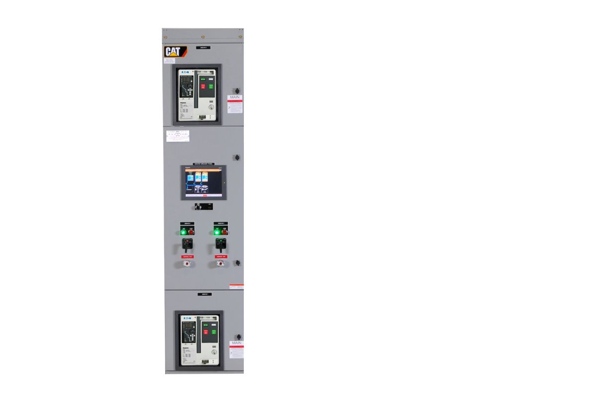
Floor Standing modular switchgear paralleling system (Master Breaker Panel for the first 2 gensets, separate structures for up to 8 additional gensets , utility, and load control/distribution)
Modes of Operation
Emergency Standby with redundant master control. Utility paralleling, peak shaving, and closed transition to/from Generator Power (with optional utility control panel)
Application
LV only (208V - 480V)
Generator Protective Devices
ANSI Protective Devices
15/25. 27/59, 81 O/U, 32, 40, 90 (Industrial Grade)
Utility Protective Devices
ANSI Protective Devices
(Utility Grade) SR-750 / SEL-351S, 25, 27/59, 81 O/U, 32,47 (Industrial Grade) 15
Environmental Parameters
Certifications
UL891
Control Panel Enclosure
NEMA1
Operating Temperature
0°C to 55°C
Storage Temperature
-20°C to 60°C
Technical Summary
Configuration
Floor Standing modular switchgear paralleling system (Master Breaker Panel for the first 2 gensets, separate structures for up to 8 additional gensets , utility, and load control/distribution)
Modes of Operation
Emergency Standby with redundant master control. Utility paralleling, peak shaving, and closed transition to/from Generator Power (with optional utility control panel)
Application
LV only (208V - 480V)
Environmental Parameters
Operating Temperature
0°C to 55°C
Storage Temperature
-20°C to 60°C
Storage Temperature
-20°C to 60°C
Features
General Features
- Automatic Start/Stop
- Automatic Load and VAR Sharing
- Automatic “Dead Bus” Coordination
- Automatic Power Factor Control When in Parallel with Utility Power
- Programmable Load Shed / Load Add Functions
- Redundant Master Functionality
- High Speed Ethernet Supervisory Network
- Networked Engine Communications
- Generator and Utility Protection
- User-Programmable Logic & I/O
- Password Security System to ensure system security
Standard Equipment
- Master Breaker Panel (MBP) for first 2 gensets
- With electrically operated generator circuit breakers, lugs or cross-bus, and genset controls
- 12" Graphical Color Touchscreen display (HMI) Instant Auto Selector Switch
- Allows user to return system to automatic in the event of a touchscreen failure
- Spare inputs and outputs
- 2 discrete inputs and 3 discrete outputs programmable from the HMI
Optional Equipment
- Generator Breaker Panel for 1 or 2 incremental gensets (up to 8 additional gensets)
- With breaker position indications, circuit breaker control switch, generator controller, and user programmable logic I/O
- Utility Breaker Panel
- With closed transition soft transfer and utility control for 1 LV circuit breaker, utility grade protective relay, utility close lockout switch, breaker position indications, and circuit breaker control switch
- Supplemental Hardware Synchronization check relay (ANSI 25 Device)
- Provides additional discrete synchronization protection
- Data Table Interface
- Accomodates interface with a building management system for monitoring all system parameters via Modbus RTU or TCP
- Generator Demand Priority Control
- Automatically match the on-line generator capacity to the loads, and avoid unnecessary operation of generator sets.
- Distribution Breaker Panel Slave
- With I/O module for control of up to 3 circuit breakers
- Each slave panel contains 3 distribution breakers
 WARNING